
Mazda CX-5 Service & Repair Manual: Front Stabilizer Removal/Installation
CAUTION:
-
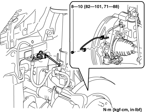
Performing the following procedures without first removing the front ABS wheel-speed sensor may possibly cause an open circuit in the wiring harness if it is pulled by mistake. Before performing the following procedures, disconnect the front ABS wheel-speed sensor wiring harness (axle side) and fix the wiring harness to an appropriate place where it will not be pulled by mistake while servicing the vehicle.
-
Secure the steering wheel using tape or a cable to prevent the steering shaft from rotating after disconnecting the steering shaft. If the steering wheel rotates after the steering shaft and the steering gear and linkage are disconnected, the internal parts of the clock spring could be damaged.
1. Remove the joint cover..
2. Disconnect the intermediate shaft from the steering gear and linkage..
3. Disconnect the front ABS wheel-speed sensor wiring harness installed to the steering knuckle and set it aside..
4. Remove in the order indicated in the table.
5. Install in the reverse order of removal.
6. Inspect the wheel alignment and adjust it if necessary..
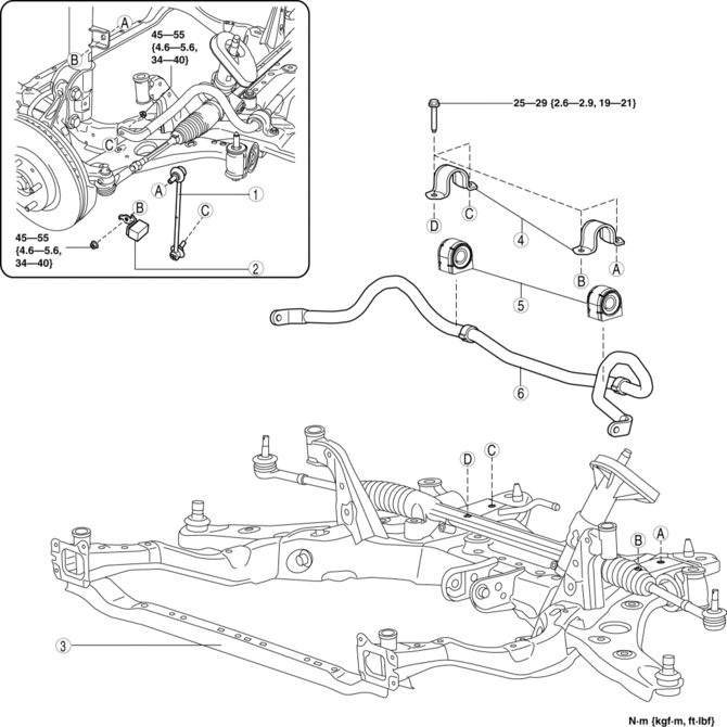
|
1 |
Front stabilizer control link |
|
2 |
Dynamic damper (if equipped) |
|
3 |
Front crossmember component (See FRONT CROSSMEMBER REMOVAL/INSTALLATION.) |
|
4 |
Front stabilizer bracket (See Front Stabilizer, Front Stabilizer Bushing and Front Stabilizer Bracket Installation Note.) |
|
5 |
Front stabilizer bushing (See Front Stabilizer Bushing, Front Stabilizer Bracket Installation Note.) (See Front Stabilizer, Front Stabilizer Bushing and Front Stabilizer Bracket Installation Note.) |
|
6 |
Front stabilizer (See Front Stabilizer, Front Stabilizer Bushing and Front Stabilizer Bracket Installation Note.) |
Front Stabilizer Bracket Removal Note
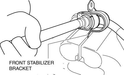
1. Secure the front stabilizer bracket flange using a vise.
Front Stabilizer Bushing, Front Stabilizer Bracket Installation Note
1. Install the front stabilizer bushing to the front stabilizer with its slit positioned rearward of the vehicle.
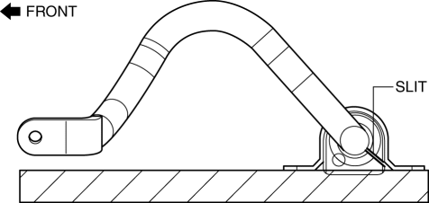
2. Install the front stabilizer bracket to the front stabilizer bushing by hand using the following procedure.
3. If the front stabilizer bracket cannot be installed by hand, install it using a vice.
CAUTION:
-
If the front stabilizer bracket is installed using a vice, it could be deformed.
-
Set a cylindrically-shaped object as shown in the figure so that pressure is applied to the front stabilizer bracket flange, and install the front stabilizer bracket to the front stabilizer bushing.
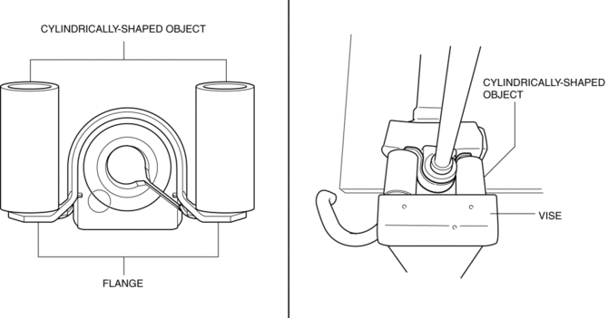
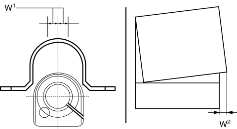
4. During front stabilizer bracket installation, keep the deviation in the positions of the front stabilizer bracket and the front stabilizer bushing within the range shown in the figure.
-
W1: 0.5 mm {0.21 in} max.
-
W2: 2 mm {0.08 in} max.
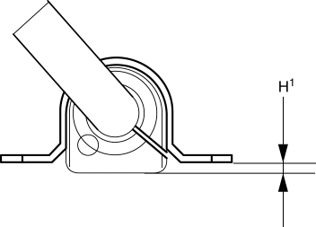
5. After installing the front stabilizer bracket, verify that the positions of the front stabilizer bracket and the front stabilizer bushing are within the range shown in the figure.
-
H1: 13 mm {0.51 in} max.
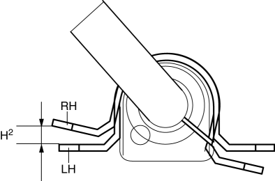
6. After installing the front stabilizer bracket, verify that the right and left-side positions of the front stabilizer bracket are within the range shown in the figure.
-
H2: 6 mm {0.2 in} max.
7. Place the front stabilizer component on a level workbench, and verify that it is within the range shown in the figure.
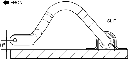
-
H3: 32.1—42.1 mm {1.27—1.65 in}
Front Stabilizer, Front Stabilizer Bushing and Front Stabilizer Bracket Installation Note
1. Temporarily tighten bolts A and B shown in the figure.
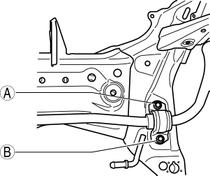
2. Tighten bolt A.
-
Tightening torque
-
25—29 N·m {2.6—2.9kgf·m, 19—21 ft·lbf}
3. Tighten bolt B.
-
Tightening torque
-
25—29 N·m {2.6—2.9kgf·m, 19—21 ft·lbf}
4. Tighten bolt A.
-
Tightening torque
-
25—29 N·m {2.6—2.9kgf·m, 19—21 ft·lbf}
 Front Stabilizer Control Link Inspection
1. Remove the front stabilizer control link..
2. Inspect for bending or damage. If there is any malfunction, replace the front
stabilizer control link.
3. Rotate the front stabilizer control lin ...
 Front Suspension
Outline
A strut type front suspension has been adopted.
The connection area of the front crossmember and body is a 6-point rigid
mount type.
The cross-section o ...
Other materials:
Clock Spring Removal/Installation [Two Step Deployment Control System]
CAUTION:
If the disc on the combination switch is deformed or has foreign material
adhering to it, performance of the steering angle sensor may be reduced, causing
abnormal operation. When handling the clock spring, be careful not to deform
the disc and make sure there is no foreign ...
Discharge Headlight Service Warnings
Discharge Headlight Service Warnings
When replacing a discharge headlight bulb, performing the servicing with
the negative battery cable connected or in a wet work area could result in electrocution.
When replacing a discharge headlight bulb, perform the servicing under the following
...
Turbine/Input Shaft Speed Sensor, Output Shaft Speed Sensor [Fw6 A EL, Fw6 Ax
EL]
Purpose/Function
The turbine/input shaft speed sensor detects the rotation speed of the input
shaft (low clutch drum).
The output shaft speed sensor detects the rotation speed of the output shaft
(primary gear).
The turbine/input shaft speed sensor and output shaft speed ...
