Mazda CX-5 Service & Repair Manual: Front Side Frame (Partial Cutting) Removal [Panel Replacement]
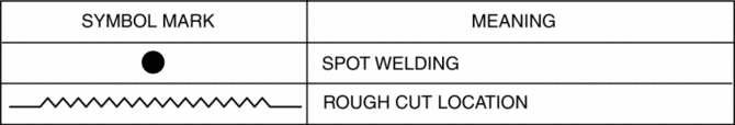
Symbol Mark
Removal Procedure
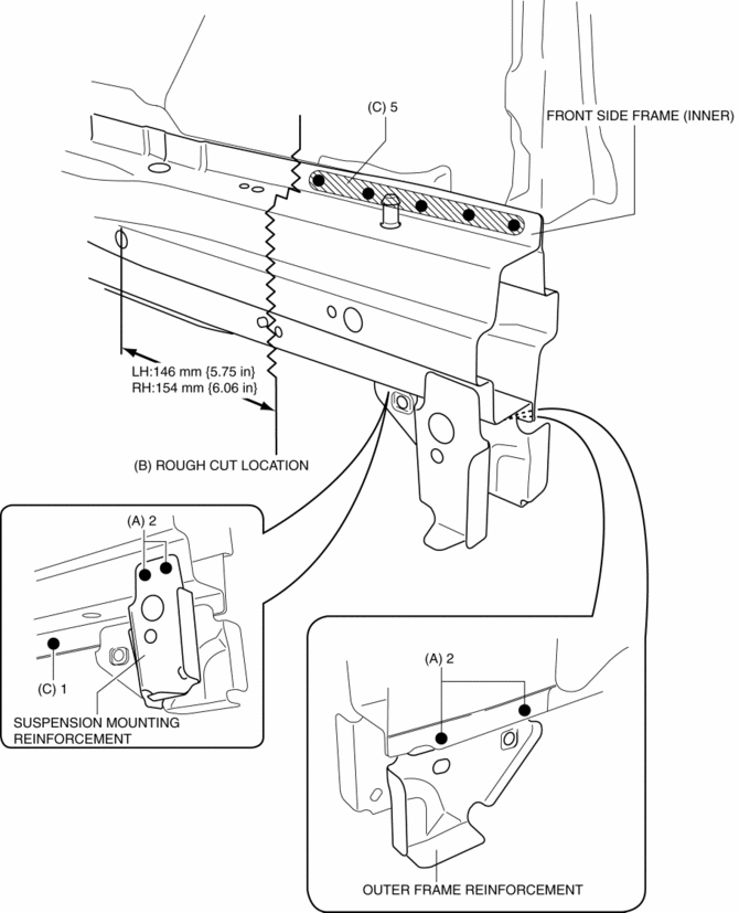
1. Drill the 4 locations indicated by (A) shown in the figure, then remove suspension mounting reinforcement and outer frame reinforcement.
2. Rough cut location indicated by (B) shown in the figure.
3. Drill the 6 locations indicated by (C) shown in the figure, then remove the front side frame (inner).
4. Rough cut location indicated by (D) shown in the figure.
5. Drill the 3 locations indicated by (E) shown in the figure.
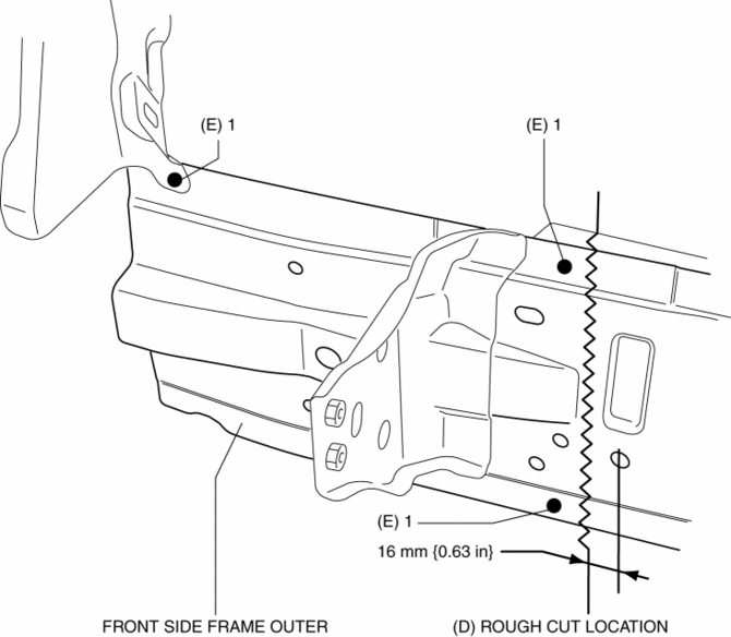
6. Remove the front side frame (outer).
 Front Side Frame (Partial Cutting) Installation [Panel Replacement]
Symbol Mark
Installation Procedure
CAUTION:
The cut and joint area indicates the maximum size range of the installation
position.
1. Drill holes for the plug welding before inst ...
 Front Side Frame Installation [Panel Replacement]
Symbol Mark
Installation Procedure
1. When installing new parts, measure and adjust the body as necessary to conform
with standard dimensions.
2. Drill holes for the plug welding before inst ...
Other materials:
Theft Deterrent Horn Inspection
1. Disconnect the negative battery cable..
2. Remove the following parts:
a. Trunk end trim.
b. Rear scuff plate (RH).
c. Trunk side trim (RH).
d. Theft-deterrent horn.
3. Apply battery positive voltage to horn terminal A, and connect the horn retaining
bolt to ground as shown in the f ...
Passenger Compartment Temperature Sensor [Full Auto Air Conditioner]
Purpose
The passenger compartment temperature sensor detects the cabin temperature.
Function
The passenger compartment temperature sensor converts the detected temperature
to an electric signal.
Construction
A thermistor-type passenger compartment temperature sens ...
Ion Sensor
Purpose/Function
Detects ion generation in the combustion chamber for detecting pre-ignition.
Detects ions which occur due to fuel combustion as current by applying bias
voltage to the spark plug, which is amplified in the ignition coil internal
circuit and input to the PCM.
...
