Mazda CX-5 Service & Repair Manual: Front Side Frame (Partial Cutting) Installation [Panel Replacement]
Symbol Mark

Installation Procedure
CAUTION:
-
The cut and joint area indicates the maximum size range of the installation position.
1. Drill holes for the plug welding before installing the new parts.
2. When installing the new parts, trial-fit new and existing parts, and then measure and adjust the body to conform with standard dimensions.
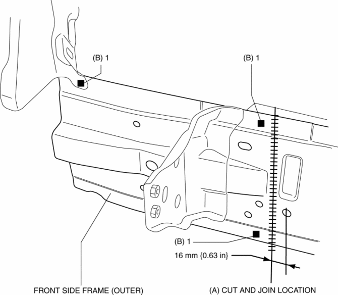
3. Cut and join location indicated by (A) shown in the figure.
4. Plug weld the 3 locations indicated by (B) shown in the figure, then install the front side frame (outer).

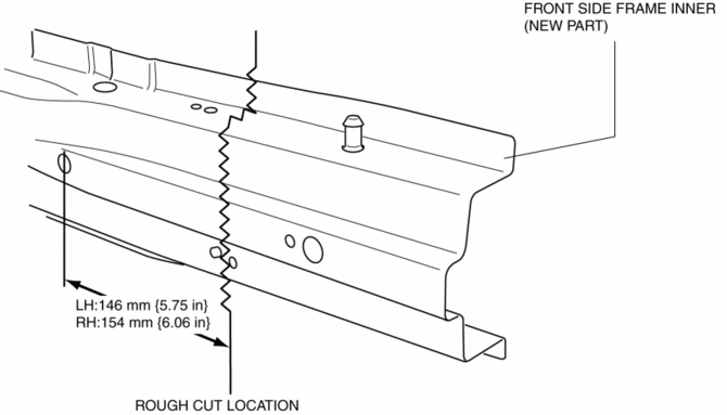
5. To cut and join the new and existing parts, rough cut the new part at the specified location shown in the figure, and chamfer the joint surfaces of the new and existing parts.

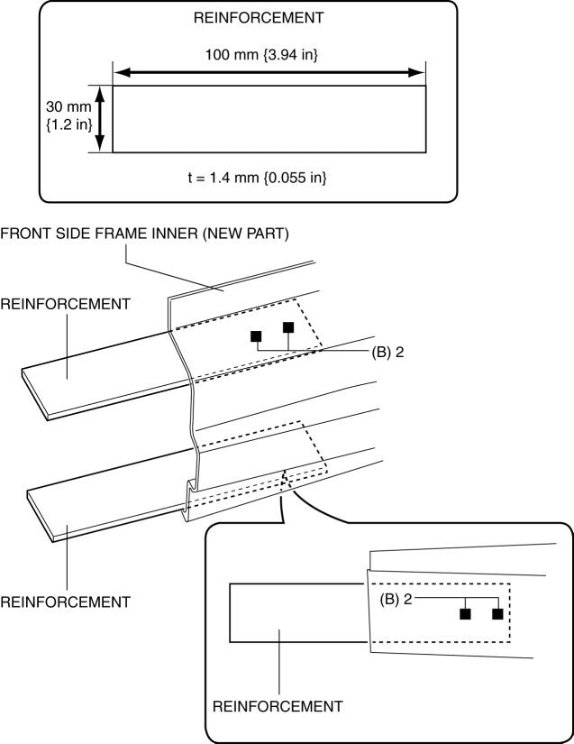
6. Make a reinforcement panel using the material from the front side frame (inner).
7. Plug weld the 4 locations indicated by (B) shown in the figure, then install the reinforcement to the new front side frame (inner).

8. Plug weld the 3 locations indicated by (C) shown in the figure.
NOTE:
-
Press fit the reinforcement panel and the body side material, and then weld them.
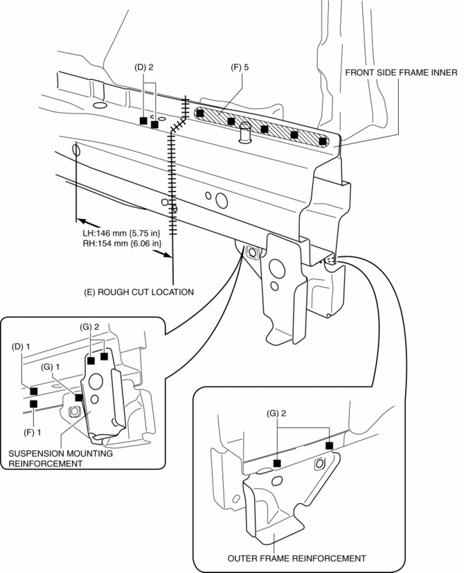
9. Cut and location indicated by (D) shown in the figure.
10. Plug weld the 6 locations indicated by (E) shown in the figure, then install the front side frame inner.
11. Plug weld the 5 locations indicated by (F) shown in the figure, then install suspension mounting reinforcement and outer frame reinforcement.

 Front Seat Cushion Frame Removal/Installation
WARNING:
Handling a side air bag improperly can accidentally operate (deploy) the
air bag, which may seriously injure you. Read the service warnings/cautions
in the Workshop Manual befor ...
 Front Side Frame (Partial Cutting) Removal [Panel Replacement]
Symbol Mark
Removal Procedure
1. Drill the 4 locations indicated by (A) shown in the figure, then remove suspension
mounting reinforcement and outer frame reinforcement.
2. Rough cut locatio ...
Other materials:
Door Locks
WARNING
Always take all children and pets with you or leave a responsible person with
them:
Leaving a child or a pet unattended in a parked vehicle is dangerous. In hot
weather, temperatures inside a vehicle can become high enough to cause brain damage
or even death.
Do not leave the key in ...
Back Up Light Bulb Removal/Installation
1. Disconnect the negative battery cable..
2. Insert a tape-wrapped flathead screwdriver into the service hole in the position
shown in the figure.
3. Move the flathead screwdriver in the direction of the arrow (1) shown in the
figure, pull out the service hole cover from the liftgate, a ...
Front Buckle Removal/Installation
Driver-side
1. Disconnect the negative battery cable and wait for 1 min or more..
2. Remove the front seat..
3. Disconnect the front buckle connector.
4. Remove the bolt.
5. Remove the front buckle.
6. Install in the reverse order of removal.
Passenger-side (with buckle switch) ...
