Mazda CX-5 Service & Repair Manual: Front Outer Handle Removal/Installation
1. Perform the front door glass preparation..
2. Disconnect the negative battery cable..
3. Remove the following parts:
a. Inner garnish.
b. Front door trim.
c. Front door glass.
d. Front door module panel.
e. Front door key cylinder.
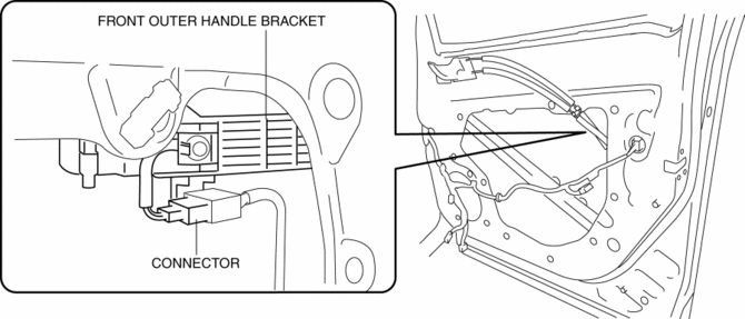
4. Disconnect the keyless antenna connector (With advanced keyless entry system).
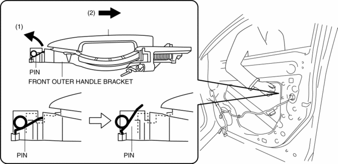
5. While pulling the front outer handle bracket pin in the direction of arrow (1) shown in the figure, pull the front outer handle in the direction of arrow (2) to detach the front outer handle bracket pin and the front outer handle.
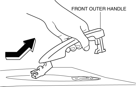
6. Remove the front outer handle in the direction of the arrow shown in the figure.
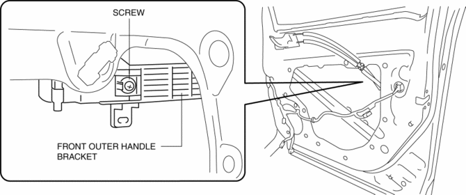
7. Loosen the screw securing the front outer handle bracket.
NOTE:
-
The screw cannot be removed because the front outer handle bracket has a stopper which prevents the screw from falling.
8. Pull the front outer handle bracket in the direction of arrow (1) shown in the figure and detach the front outer handle bracket hooks from the body.
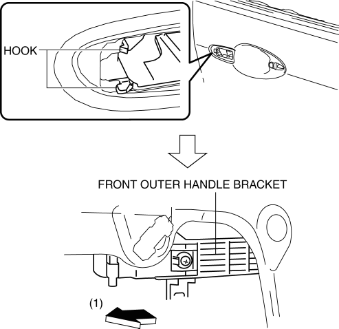
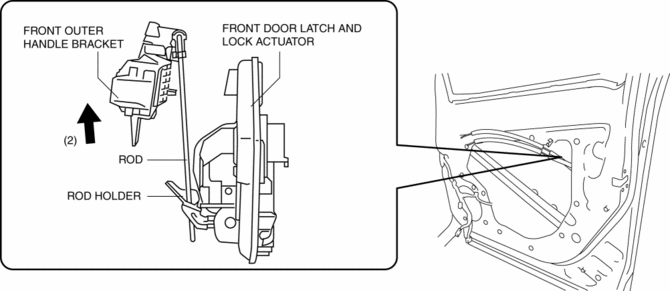
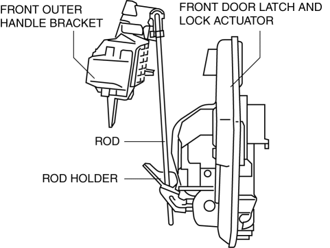
9. Lift the front outer handle bracket in the direction of arrow (2) shown in the figure to pull the rod out of the rod holder..
10. Remove the front outer handle bracket.
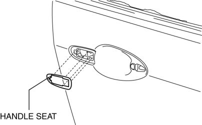
11. Remove the handle seat from the body.
12. Install in the reverse order of removal.
Front Outer Handle Bracket Installation Note
-
To assure that the rod is inserted into the rod holder hole, verify that the there is no excessive play.
 Front Door Removal/Installation
WARNING:
Removing the front door without supporting it could cause the front door
to fall and cause serious injury. Always perform the procedure with at least
one other person to prevent ...
 Hood
Hood
Purpose/Function
The hood is constructed with a large space between the front end of the hood
and the engine to absorb an impact.
Construction
The hood stiffener positioned at t ...
Other materials:
Clock Spring Adjustment [Standard Deployment Control System]
1. Set the front wheels straight ahead.
CAUTION:
The clock spring will break if over?wound. Do not forcibly turn the clock
spring.
2. Turn the clock spring clockwise until it stops.
3. Turn the clock spring counterclockwise approx. 2 turns.
4. Align the mark on the clo ...
Manifold Absolute Pressure (Map) Sensor/Intake Air Temperature (Iat) Sensor
No.2 Removal/Installation
NOTE:
Because the IAT sensor No.2 is integrated in the MAP sensor, replacing the
IAT sensor No.2 includes replacement of the MAP sensor/IAT sensor No.2.
1. Disconnect the negative battery cable..
2. Disconnect the MAP sensor/IAT sensor No.2 connector.
3. Remove the MAP sensor/IA ...
Front Drive Shaft Inspection
1. Inspect the connections for any looseness.
If there is any malfunction, tighten or replace the applicable part.
2. Inspect the dust boot for damage and cracks.
If there is any malfunction, replace the applicable part.
3. Move the spline and joint up and down, left ...
