
Mazda CX-5 Service & Repair Manual: Front Door Trim Disassembly/Assembly
Driver-side
1. Disassemble in the order shown in the figure.
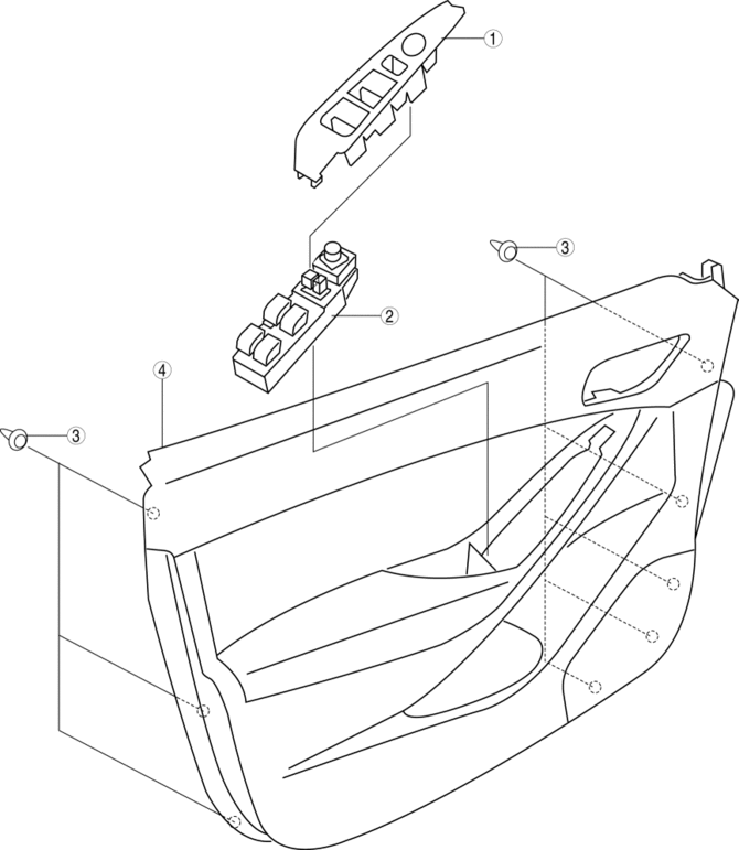
|
1 |
Switch panel cover |
|
2 |
Power window main switch (See Power Window Main Switch, Power Window Subswitch And Lock Switch Removal Note.) |
|
3 |
Fastener |
|
4 |
Front door trim |
2. Assemble in the reverse order of disassembly.
passenger-side
1. Disassemble in the order shown in the figure.
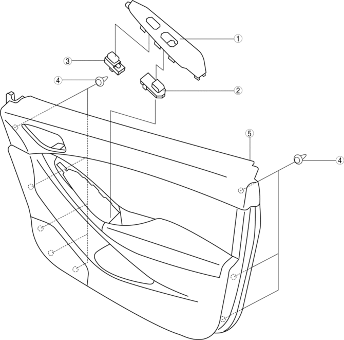
|
1 |
Switch panel cover |
|
2 |
Power subswitch (See Power Window Main Switch, Power Window Subswitch And Lock Switch Removal Note.) |
|
3 |
Lock switch (See Power Window Main Switch, Power Window Subswitch And Lock Switch Removal Note.) |
|
4 |
Fastener |
|
5 |
Front door trim |
2. Assemble in the reverse order of disassembly.
Power Window Main Switch, Power Window Subswitch And Lock Switch Removal Note
1. Pull the edge of power window main switch or subswitch cover in the direction of arrow (1) and detach tabs.
Driver-side
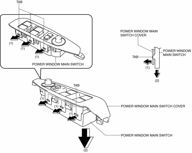
Passenger-side
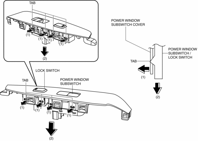
2. Remove the power window main switch, power window subswitch or lock switch in the direction of arrow (2) shown in the figure.
 Rear Door Latch And Lock Actuator Inspection
The following actuator and switch are integrated with the rear door latch
and lock actuator.
From the actuator/switch name and operation in the following table, select
the actu ...
 Front Door Trim Removal/Installation
1. Disconnect the negative battery cable..
2. Remove the inner garnish..
3. Insert a tape-wrapped flathead screwdriver in the position indicated by the
arrow (1) in the figure and remove the inn ...
Other materials:
Airflow Mode Actuator Removal/Installation [Full Auto Air Conditioner]
1. Disconnect the negative battery cable..
2. Remove the following parts:
a. Dashboard under cover.
b. Glove compartment.
3. Disconnect the airflow mode actuator connector.
4. Remove the screw.
5. Remove the airflow mode actuator.
6. Remove the airflow mode main link.
7. Remo ...
Aerodynamic
Purpose/Function
For improved aerodynamics, under covers are installed to the under-surface
of the vehicle.
Construction
The vehicle is equipped with the following (3) under covers.
Front under cover No.1
Front under cover No.2
Floor under co ...
Clock Inspection
1. Disconnect the negative battery cable..
2. Remove the following parts:
a. Shift lever knob (MTX).
b. Front console box.
c. Shift panel.
d. Upper panel.
e. Rear console.
f. Side wall.
g. Decoration panel.
h. Front console.
i. Glove compartment.
j. Climate control unit.
3. C ...
