Mazda CX-5 Service & Repair Manual: Front ABS Wheel Speed Sensor Inspection
Sensor Output Value Inspection
CAUTION:
-
Resistance inspection using other testers may cause damage to the ABS wheel-speed sensor internal circuit. Be sure to use the M-MDS to inspect the ABS wheel-speed sensor.
1. Switch the ignition to off.
2. Connect the M-MDS to the DLC-2.
3. Select the following PIDs using the M-MDS:
-
WSPD_SEN_LF (LF wheel-speed sensor)
-
WSPD_SEN_RF (RF wheel-speed sensor)
4. Start the engine and drive the vehicle.
5. Verify that the display of the M-MDS shows the same value as the speedometer.
-
If there is any malfunction, replace the ABS wheel-speed sensor.
Installation Visual Inspection
1. Inspect for the following:
-
If there is any malfunction, replace the part.
a. Excessive play of the ABS wheel-speed sensor
b. Deformation of the ABS wheel-speed sensor
c. Deformation or damage of the ABS sensor rotor
Clearance Inspection
Preparation prior to inspection
1. Remove the ABS wheel-speed sensor..
2. Remove the wheel hub and steering knuckle as a single unit..
3. Install the ABS wheel-speed sensor to the removed wheel hub, steering knuckle component, and tighten to the specified torque.
-
Tightening torque
-
8—10 N·m {82—101 kgf·cm, 71—88 in·lbf}
Clearance Inspection
1. Measure the gap between the ABS sensor rotor and ABS wheel-speed sensor using a feeler gauge.
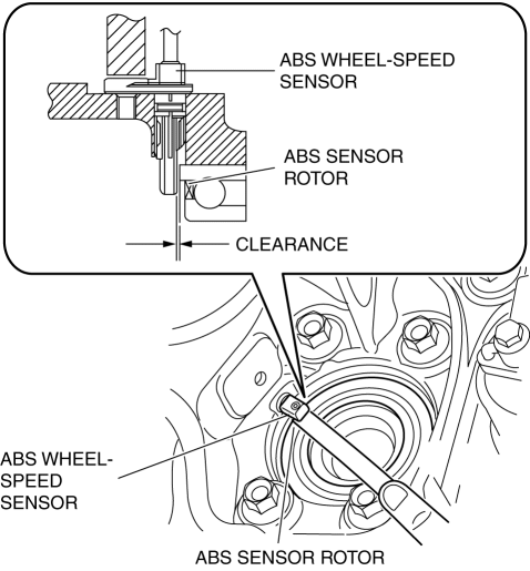
-
If not within the specification, verify the following items and repair or replace if necessary.
-
Is there deformation or damage to the ABS sensor rotor?
-
Is there deformation or damage to the ABS wheel speed sensor?
-
Is there foreign material adhering?
-
Clearance
-
0.87—1.53 mm {0.035—0.060 in}
Servicing after inspection
1. Remove the ABS wheel-speed sensor from the wheel hub, steering knuckle component.
2. Install the wheel hub, steering knuckle component..
3. Install the ABS wheel-speed sensor..
4. Inspect the front wheel alignment..
 Brake System/ABS Warning Light
Purpose/Function
The brake system/ABS warning light is built into the instrument cluster.
If a malfunction is detected in the system with the parking brake released,
the warning light ill ...
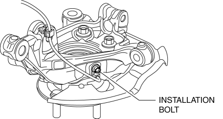
 Front ABS Wheel Speed Sensor Removal/Installation
1. Remove the mudguard..
2. Remove in the order indicated in the table.
3. Install in the reverse order of removal.
4. After installation, verify that there is no twisting in the front ABS wheel ...
Other materials:
Blind Spot Monitoring (Bsm) Off Switch
Purpose
The blind spot monitoring (BSM) system can be turned on or off optionally
by the driver.
Function
The switch operation signal is sent to the instrument cluster.
Construction
The BSM OFF switch is built into the cluster switch.
The resistance is bui ...
Fuel Gauge Sender Unit Inspection [Awd]
Fuel gauge sender unit (main)
NOTE:
For the fuel gauge sender unit removal/installation, refer to the fuel pump
removal/installation because the fuel gauge sender unit is integrated with the
fuel pump..
1. Verify that the resistance at fuel gauge sender unit (main) terminals D a ...
Neutral Switch
Purpose/Function
Detects the neutral position of the shift lever.
Construction
Installed to the manual transaxle.
An ON/OFF type switch has been adopted.
Operation
Inputs the neutral switch on/off signal to the PCM.
The contact point is on ...
