
Mazda CX-5 Service & Repair Manual: Evaporative Emission (Evap) Control System
Purpose, Outline
-
Prevents release of evaporative gas into the atmosphere.
-
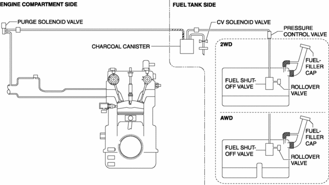
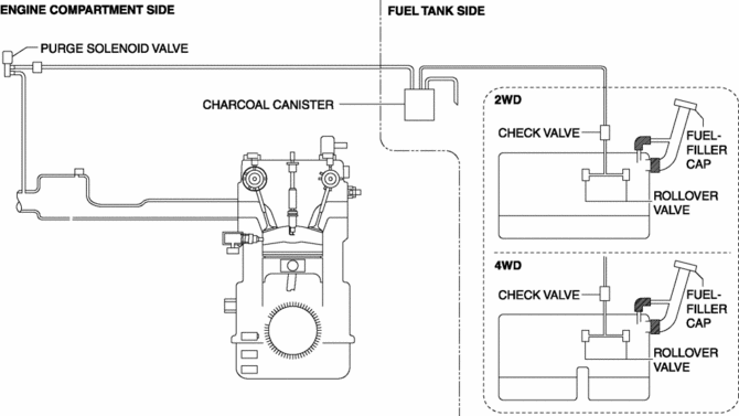
The intake manifold vacuum introduces evaporative gas to the intake manifold via the charcoal canister and the purge solenoid valve.
System Diagram
U.S.A. and CANADA
Except U.S.A. and CANADA
Structure
-
The evaporative emission control system consists of the following parts:
|
Part name |
Reference |
|
Purge solenoid valve |
(See PURGE SOLENOID VALVE [SKYACTIV-G 2.0].) |
|
Catch tank |
(See CATCH TANK [SKYACTIV-G 2.0].) |
|
Charcoal canister |
(See CHARCOAL CANISTER [SKYACTIV-G 2.0].) |
|
Pressure control valve |
(See PRESSURE CONTROL VALVE [SKYACTIV-G 2.0].) |
|
Fuel shut-off valve |
(See FUEL SHUT-OFF VALVE [SKYACTIV-G 2.0].) |
|
Rollover valve |
(See ROLLOVER VALVE [SKYACTIV-G 2.0].) |
|
Fuel-filler cap |
(See FUEL-FILLER CAP [SKYACTIV-G 2.0].) |
|
CV solenoid valve |
(See CANISTER VENT (CV) SOLENOID VALVE [SKYACTIV-G 2.0].) |
Except U.S.A. and CANADA
|
Part name |
Reference |
|
Purge solenoid valve |
(See PURGE SOLENOID VALVE [SKYACTIV-G 2.0].) |
|
Catch tank |
(See CATCH TANK [SKYACTIV-G 2.0].) |
|
Charcoal canister |
(See CHARCOAL CANISTER [SKYACTIV-G 2.0].) |
|
Check valve |
(See CHECK VALVE [SKYACTIV-G 2.0].) |
|
Rollover valve |
(See ROLLOVER VALVE [SKYACTIV-G 2.0].) |
|
Fuel-filler cap |
(See FUEL-FILLER CAP [SKYACTIV-G 2.0].) |
 Emission System
Purpose, Outline
A single-nano catalyst has been adopted for the under-floor, three-way catalyst
to improve emission gas purification efficiency.
Structural View
Engine compartment si ...
 Exhaust Gas Purification System
Purpose, Outline
Purifies contaminants (HC, CO, NOx) in the exhaust gas by utilizing the chemical
reactions of the three-way catalytic converter.
System Diagram
Structure
T ...
Other materials:
Clutch Disc Inspection [C66 M R]
Operation Inspection
1. Inspect the lining surface for discoloration and grease adhesion.
2. Inspect the torsion spring for weakness and the rivets for looseness.
3. Using a vernier caliper, measure the depth between the lining surface and
the rivet head.
Minimum clutch disc thicknes ...
Canister Vent (Cv) Solenoid Valve Removal/Installation
U.S.A. And CANADA
1. Disconnect the negative battery cable..
2. Remove the floor under cover (LH)..
3. Disconnect the evaporative hose No.2..
4. Remove in the order indicated in the table.
1
CV solenoid valve connector
2
CV solenoid va ...
Front Side Frame (Partial Cutting) Installation [Panel Replacement]
Symbol Mark
Installation Procedure
CAUTION:
The cut and joint area indicates the maximum size range of the installation
position.
1. Drill holes for the plug welding before installing the new parts.
2. When installing the new parts, trial-fit new and existing parts, and then ...
