Mazda CX-5 Service & Repair Manual: Electric Variable Valve Timing Relay [Skyactiv G 2.0]
Purpose, Function
-
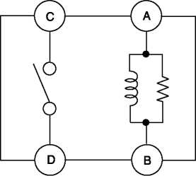
The electric variable valve timing actuator relay supplies power to the electric variable valve timing motor/driver after receiving the signal from the PCM.
Construction
-
The electric variable valve timing actuator relay is installed to the relay block..
Operation
1. When current flows between A—B shown in the figure, electromagnetic power is generated, the switch between C—D is turned on, and the current flows between C—D.
2. Current flows between C—D and power is supplied to the electric variable valve timing motor/driver.

Fail-safe
-
Function not equipped.
 Corner Junction Removal [Panel Replacement]
Symbol Mark
Removal Procedure
1. Drill the 27 locations shown in the figure.
2. Remove the corner junction. ...
 Front Fender Junction Installation [Panel Replacement]
Symbol Mark
Installation Procedure
1. When installing new parts, measure and adjust the body as necessary to conform
with standard dimensions.
2. Drill holes for the plug welding before inst ...
Other materials:
R 3 5 Brake [Fw6 A EL, Fw6 Ax EL]
Purpose/Function
The R-3-5 brake operates in 3GR, 5GR and in reverse to lock the reduction
internal gear against rotation.
Construction
The R-3-5 brake consists of the following parts shown in the figure.
The driven plate of the R-3-5 brake does not rotate be ...
Blower Motor [Full Auto Air Conditioner]
Purpose
The blower motor sends airflow into the cabin.
Function
The blower motor rotates the blower fan to create airflow and sends out the
airflow in the blower unit and A/C unit.
Construction
The blower motor is installed to the blower unit.
The blower m ...
Shift Pressure Control (Line Pressure Control) [Fw6 A EL, Fw6 Ax EL]
Outline
The TCM drives the pressure control solenoid and adjusts the pressure based
on the accelerator pedal depression amount, vehicle speed, ATF temperature,
and gear shift signal. As a result, line pressure is controlled finely and with
high accuracy according to the engine load c ...
