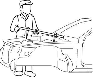
Mazda CX-5 Service & Repair Manual: Efficient Installation Of Body Panels
Checking Preweld Measurements And Watching
-
Align to the standard reference dimensions, based upon the body dimensions illustration, so that new parts are installed in the correct position.
Welding Notes
-
For the number of weld points, welding should be performed in accordance with the following reference standards.
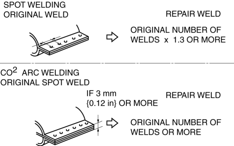
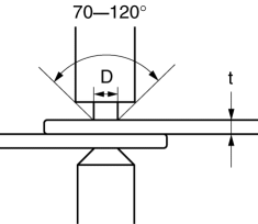
Spot Welding Notes
-
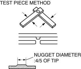
The shape of the spot welder tip is D=(2?t)+3. If the upper panel thickness is different from that of the under panel, adjust to the thinner one.
-
Because the weld strength is affected by the shape of the spot welder tip, the optimum condition of the tip should always be maintained.
-
Spot welds should be made at points other than the originally welded points.
-
Before spot welding, make a trial weld using the same material as the body panel to check the weld strength.
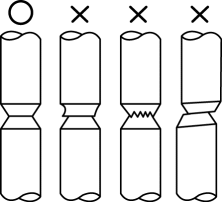
Checking Weld Strength
-
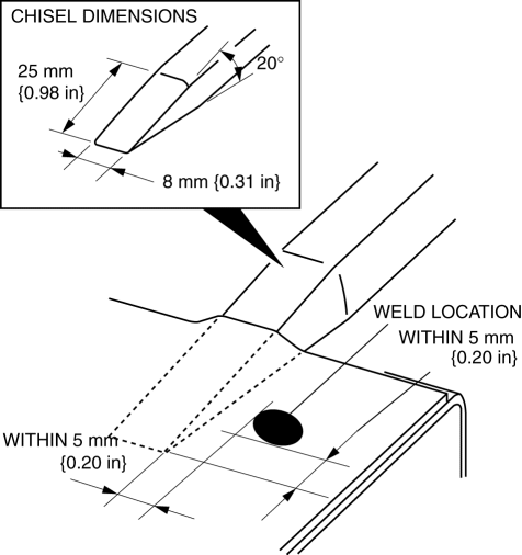
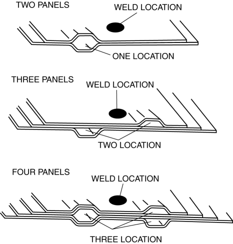
Installation locations of the engine, chassis, and seat belts are designated as important safety locations for weld strength. Check weld strength by driving a chisel between the panels at every fourth or fifth weld spot, and every tenth regular weld location.
-
Drive the chisel between the panels according to the number of panels as shown below.
-
To determine weld strength, drive the chisel between the panel and check whether the panels come apart. If the panels come apart, make another weld near the original weld.
-
Restore the shape of the checked area.
 D Pillar Reinforcement (Lower) Removal [Panel Replacement]
Symbol Mark
Removal Procedure
1. Drill the 8 locations shown in the figure.
2. Remove the D-pillar reinforcement (lower). ...
 Efficient Removal Of Body Panels
Body Measurements
Before removal or rough?cutting, first measure the body at and around the
damaged area against the standard reference dimension specifications. If there
is deformation, ...
Other materials:
Fuel Injection Control System
Outline
Performs optimum fuel injection according to engine operation conditions.
The PCM determines the engine operation conditions based on the signals from
each input device and drives the fuel injectors at the optimal fuel injection
time (fuel injection amount) and the fuel ...
Charcoal Canister Removal/Installation
U.S.A. And CANADA
1. Disconnect the negative battery cable..
2. Remove the floor under cover..
3. Remove in the order indicated in the table.
1
Quick release connector
(See QUICK RELEASE CONNECTOR (EMISSION SYSTEM) REMOVAL/INSTALLATION [SKYACTIV-G
2.0].)
...
Rear Seat Belt Removal/Installation
CAUTION:
The ELR (emergency locking retractor) has a spring that will unwind if the
retractor cover is removed. The spring cannot be rewound by hand. If this occurs,
the ELR will not work properly. Therefore, do not disassemble the retractor.
1. Remove the following parts:
a. T ...
