
Mazda CX-5 Service & Repair Manual: D Pillar Reinforcement (Lower) Installation [Panel Replacement]
Symbol Mark

Installation Procedure
1. When installing new parts, measure and adjust the body as necessary to conform with standard dimensions.
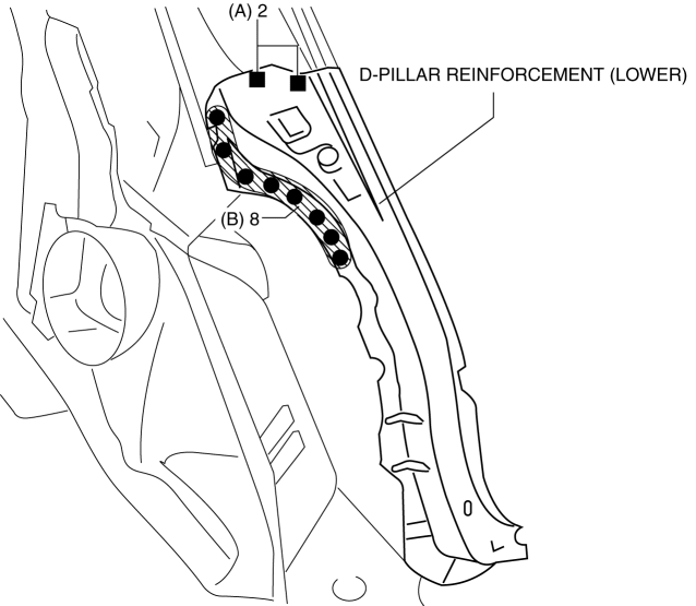
2. Drill holes for the plug welding before installing the new parts.
3. After temporarily installing new parts, make sure the related parts fit properly.
4. Plug weld the 2 locations indicated by (A) shown in the figure.
5. Spot weld the 8 locations indicated by (B) shown in the figure, then install the D-pillar reinforcement (lower).
 Cowl Upper Plate Removal [Panel Replacement]
Symbol Mark
Removal Procedure
1. Drill the 9 locations indicated by (A) shown in the figure.
2. Drill the 2 locations by (B) from the front wheel housing side shown in the
figure.
3. Drill ...
 D Pillar Reinforcement (Lower) Removal [Panel Replacement]
Symbol Mark
Removal Procedure
1. Drill the 8 locations shown in the figure.
2. Remove the D-pillar reinforcement (lower). ...
Other materials:
Shift Pressure Control (Direct Electric Shift Control) [Fw6 A EL, Fw6 Ax EL]
Outline
The TCM drives shift solenoids No.1, 2, 3, 4, the pressure control solenoid,
and the on/off solenoid based on inputs signals from each switch and sensor,
and performs direct electronic control of the clutch engagement pressure. As
a result, precise hydraulic pressure control ...
Audio Unit Personalization Features Setting Procedure
Door Locks Systems
1. Switch the ignition ON (engine off or on).
2. Turn the audio unit power on.
3. Select the following from the audio unit screen.
a. “Setup”
b. “Vehicle”
c. “Door Locks“
4. Select the following items and change the setting.
Advanced keyless entry system ...
Fuel Filler Pipe Removal/Installation
WARNING:
Fuel is very flammable liquid. If fuel spills or leaks from the pressurized
fuel system, it will cause serious injury or death and facility breakage. Fuel
can also irritate skin and eyes. To prevent this, always complete the “Fuel
Line Safety Procedure”, while referring ...
