Mazda CX-5 Service & Repair Manual: Cylinder Head
Outline
-
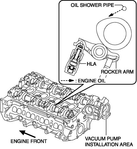
With the adoption of the rocker arm (built into needle roller bearing), the sliding resistance has been reduced.
-
With the adoption of the HLA, the valve clearance is maintained at 0 mm at all the times.
-
The contact point of the rocker arm and cam is lubricated by the engine oil injected from the oil shower pipe.
-
Because the SKYACTIV-G 2.0 is implemented on the Miller cycle, the intake manifold vacuum is insufficient during the intake valve opening timing. To improve this, the intake manifold vacuum insufficiency is supplemented with the adoption of the vacuum pump..

Purpose, Function
-
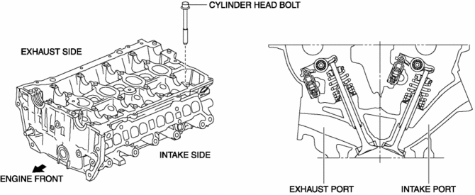
The cylinder head forms the combustion chamber and intake and exhaust ports.
Construction
-
The lightweight cylinder head is made of aluminum alloy with excellent thermal conductivity.
-
Designing a compact pentroof combustion chamber and positioning the spark plugs on the top of the combustion chamber has improved the combustion efficiency.
-
There are two intake valves and two exhaust valves per cylinder for a total of four valves and the intake/exhaust type has been changed to a cross-flow type, improving intake and exhaust efficiency.
-
High pressurization is achieved by optimizing the intake port shape, improving the tumble ratio, increasing the combustion speed, and suppressing knocking.
-
With the adoption of plastic region tightening* for the cylinder head bolts, axial force has been stabilized.

 Cylinder Head Gasket
Purpose, Function
The cylinder head gasket is installed between the cylinder head and cylinder
block to prevent leakage of air-fuel mixture, combustion gas, engine oil, and
engine coolant ...
 Hydraulic Lash Adjuster (Hla) Inspection
HLA Troubleshooting
Item
Occurrence
Possible cause
Action
1
After replacing oil, sound occurs when starting engine
...
Other materials:
Starter [Skyactiv G 2.0]
Purpose, Function
The starter rotates the crankshaft via the ring gear and it serves as a trigger
to start the engine.
Construction
The starter is installed to the rear part of the engine on the left side.
The starter is a coaxial reduction type which can obt ...
High Pressure Fuel Pump Inspection
NOTE:
The following vacuum values are indicated by relative pressure from the fuel
pressure sensor.
1. Verify that the fuel pressure sensor is normal..
2. Connect the M-MDS to the DLC-2.
3. Switch the ignition ON (engine off).
4. Select the “FUEL_PRES”, “LOAD” and “R ...
Engine Oil Pressure Warning Light
Purpose
The engine oil pressure warning light warns the driver that the engine oil
level is insufficient.
Function
When the instrument cluster receives the engine oil pressure warning light
request signal sent from the PCM via the CAN signal, it illuminates the engine
oi ...
