Mazda CX-5 Service & Repair Manual: Crankshaft, Main Bearing
Purpose, Function
-
The crankshaft converts the reciprocating movement of the piston to a rotational movement via the connecting rod.
-
The main bearing forms an oil film on the outer surface of the crankshaft journal to prevent wear due to sliding.
Construction
Crankshaft
-
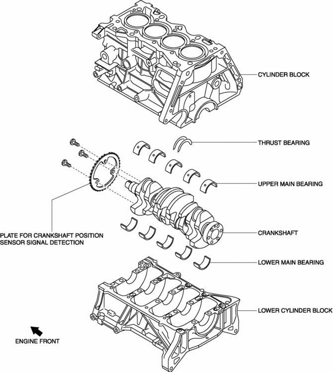
The crankshaft is installed to the inside (crankcase) of the cylinder block.

-
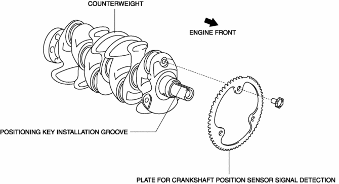
The crankshaft has a key groove to match timing to the crankshaft pulley.
-
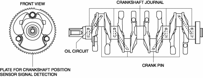
The crankshaft has the following parts shown in the figure.

-
The optimized shaft diameter ratio of the crankshaft journal and crank pin has reduced sliding resistance while maintaining rigidity.
-
The steel crankshaft has five bearings and eight counterweights for improved accuracy in the rotational balance.
-
The crankshaft journal and crank pin have been induction hardened* to bear high loads.
-
The crankshaft has an oil passage for supplying engine oil to the crankshaft journal and crank pin.

Main bearing
-
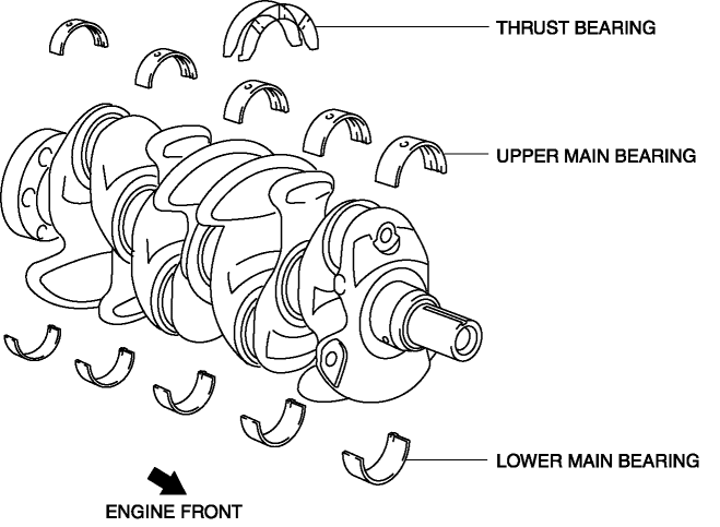
The main bearing is installed to the outer surface of the crankshaft journal.
-
The upper main bearing and lower main bearing are made of aluminum alloy.
-
The upper main bearing has an oil groove and oil hole.
-
Thrust force is suppressed by the thrust bearings on both sides of the No.3 journal.

 Crankshaft Position (CKP) Sensor
Purpose/Function
Detects the crankshaft speed as basic information for mainly determining
the fuel injection timing and ignition timing.
Detects the crankshaft speed and inputs it to ...
 Motor Mounts
...
Other materials:
Front Fog Light Aiming
NOTE:
Perform front fog light aiming if any of the following work is performed.
Front fog light replacement
Work that can affect vehicle height such as suspension replacement or
removal/installation.
1. Empty the vehicle by having all occupants leave ...
Power Windows
The ignition must be switched ON for the power windows to operate.
WARNING
Make sure the opening is clear before closing a window:
Closing power windows are dangerous. A person's hands, head, or even neck could
be caught by the window and result in serious injury or even death. This warning ...
Resistor Inspection [Manual Air Conditioner]
1. Verify that the resistance between the resistor terminals is as shown in the
table.
If there is any malfunction, replace the resistor.
Terminal
Resistance (ohm)
A—D
0.35—0.41
A—B
0. ...
