Mazda CX-5 Service & Repair Manual: Clutch Pipe And Hose Removal/Installation [C66 M R]
CAUTION:
-
Do not allow clutch fluid to get on a painted surface. Clutch fluid contains properties which can dissolve the paint. If clutch fluid gets on a painted surface, wash it off with water immediately and wipe the area off completely.
1. Disconnect the negative battery cable..
2. Remove the air cleaner component. (ex: air cleaner, air hose).
3. Remove the battery component. (ex: battery, battery tray and PCM component).
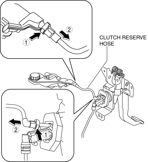
4. Remove the clutch reserve hose while pressing the point indicated by the arrow in the figure.

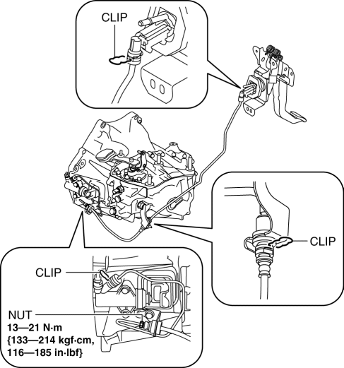
5. Remove the clutch pipe and hose (No.1 and No.2) using the following procedure:

a. Lift the connector clip.
b. Pull out the clutch pipe and hose (No.1 and No.2) connector straight to detach it.
c. Remove the clutch pipe and hose (No.1 and No.2).
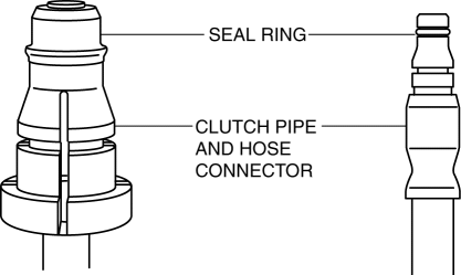
6. Verify that the seal ring is installed to the clutch pipe and hose connector.

CAUTION:
-
When removing the clutch pipe and hose, the seal ring for the clutch pipe and hose could remain on the receiving area of the connector. If the clutch pipe and hose is assembled under this condition, it could cause clutch fluid leakage from the connector.
7. Install the clutch pipe and hose (No.1 and No.2).
a. Press in the connector clip.
b. Insert the clutch pipe and hose (No.1 and No.2) connector straight.
NOTE:
-
When the connector is engaged, a click sound is heard.
c. Install the clutch pipe and hose (No.1 and No.2).
8. Insert the clutch reserve hose connector straight.
NOTE:
-
When the connector is engaged, a click sound is heard.
9. Pull each engagement of the clutch reserve hose and clutch pipe and hose No.1 and 2, verify that they are engaged, and then press all of them again.
10. Install in the reverse order of removal.
11. Bleed the air from the clutch system..
 Clutch Pedal Removal/Installation [C66 M R]
CAUTION:
Secure the steering wheel using tape or a cable to prevent the steering shaft
from rotating after disconnecting the steering shaft. If the steering wheel
rotates after the steer ...
 Clutch Release Collar Inspection [C66 M R]
CAUTION:
Do not clean the clutch release collar with cleaning fluids or a steam cleaner
because it is filled with grease.
Operation Inspection
1. Turn the collar while applying force ...
Other materials:
Hood Disassembly/Assembly
1. Disassemble in the order indicated in the table.
1
Fastener
2
Hood insulator
3
Shroud seaming welt
4
Weather strip parting seal
5
Hood component
...
Crankshaft Position (CKP) Sensor
Purpose/Function
Detects the crankshaft speed as basic information for mainly determining
the fuel injection timing and ignition timing.
Detects the crankshaft speed and inputs it to the PCM as a CKP signal.
Construction
Installed on the side of the cylinder block (ri ...
Brakes
Abbreviations
AAS
Active Adaptive Shift
ABS
Antilock Brake System
ABDC
After Bottom Dead Center
ACC
Accessories
AFS
Adaptive Front Lighting System
...
