Mazda CX-5 Service & Repair Manual: Clock Spring Removal/Installation [Two Step Deployment Control System]
CAUTION:
-
If the disc on the combination switch is deformed or has foreign material adhering to it, performance of the steering angle sensor may be reduced, causing abnormal operation. When handling the clock spring, be careful not to deform the disc and make sure there is no foreign material on it.
1. Switch the ignition to off.
2. Disconnect the negative battery cable and wait for 1 min or more
..
3. Remove the driver?side air bag module..
4. Remove the steering wheel..
5. Remove the column cover..
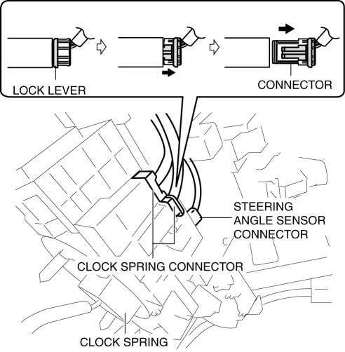
6. Disconnect the clock spring connector.

7. Disconnect the steering angle sensor connector. (with steering angle sensor)
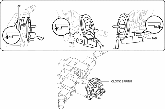
8. Remove the tab direction of the arrow shown in the figure and remove the clock spring.

9. Install in the reverse order of removal..
10. Verify that the air bag system warning light illuminates for approx. 6 s
and goes out.
-
If the air bag system warning light does not operate in the manner described above, there are malfunctions in the system. Inspect the system using the on-board diagnostic..
Clock Spring Installation Note
CAUTION:
-
If the clock spring is not adjusted, the spring wire in the clock spring will break due to overtension when the steering wheel is turned. Always adjust the clock spring after installing it.
-
Adjust the clock spring after installing it..
 Clock Spring Removal/Installation [Standard Deployment Control System]
CAUTION:
If the disc on the combination switch is deformed or has foreign material
adhering to it, performance of the steering angle sensor may be reduced, causing
abnormal operation. Wh ...
 Instrument Cluster
Outline
The instrument cluster centrally controls the speedometer, tachometer, odometer/tachometer,
fuel gauge, warning/indicator lights, trip computer, warning sounds and panel
lights.
...
Other materials:
Aerodynamic
Purpose/Function
For improved aerodynamics, under covers are installed to the under-surface
of the vehicle.
Construction
The vehicle is equipped with the following (3) under covers.
Front under cover No.1
Front under cover No.2
Floor under co ...
High Pressure Fuel Pump Control
Outline
Changes the fuel pressure applied to the fuel injector according to engine
operation conditions to improve engine output and startability.
The PCM determines the fuel pressure value corresponding to the engine operation
conditions based on the each input signal, and driv ...
Door Trim
Purpose/Function
The front and rear door trims are equipped with shock absorbing pads for
impulse force relief during a collision.
Construction
Shock absorbing pads are installed inside the front and rear door trims.
Shock absorbing pads absorb the impulse force during ...
