Mazda CX-5 Service & Repair Manual: Clock Spring Inspection [Standard Deployment Control System]
1. Disconnect the negative battery cable and wait for 1 min or more
..
2. Remove the driver?side air bag module..
3. Remove the steering wheel..
4. Remove the column cover..
5. Remove the clock spring..
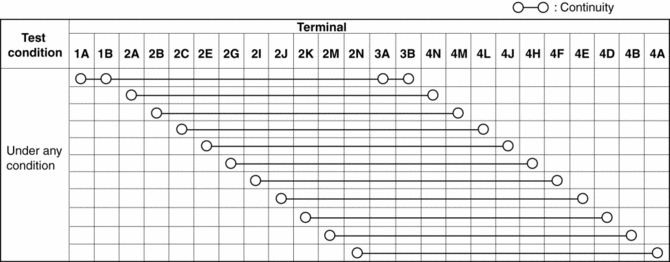
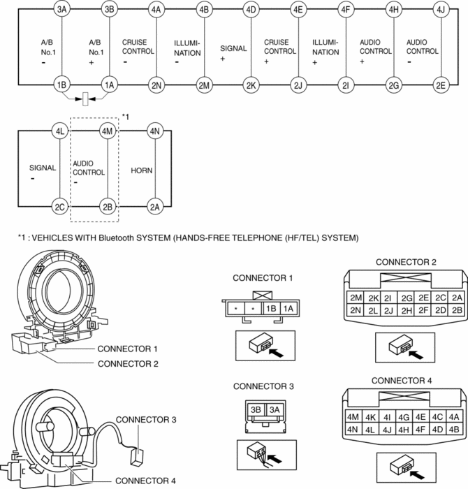
6. Verify that the continuity is as indicated in the table.
-
If not as indicated in the table, replace the clock spring.
NOTE:
-
When the vehicle-side connector for the clock spring is disconnected, terminals 1A and 1B are shorted to prevent unexpected operation (deployment) of the air bag module.
 Clock Spring Adjustment [Two Step Deployment Control System]
1. Set the front wheels straight ahead.
CAUTION:
The clock spring will break if over?wound. Do not forcibly turn the clock
spring.
2. Turn the clock spring clockwise until it stops. ...
 Clock Spring Inspection [Two Step Deployment Control System]
1. Disconnect the negative battery cable and wait for 1 min or more..
2. Remove the driver?side air bag module..
3. Remove the steering wheel..
4. Remove the column cover..
5. Remove the cloc ...
Other materials:
Entertainment System
Outline
The following entertainment system has been adopted.
Audio system (with audio system)
Car-navigation system (with car-navigation system)
Park assist system (with park assist system)
Bluetooth system (with Bluetooth system)
...
Suspension Abbreviations
AAS
Active Adaptive Shift
ABS
Antilock Brake System
ABDC
After Bottom Dead Center
ACC
Accessories
AFS
Adaptive Front Lighting System
ALC
...
Piston, Piston Ring, Piston Pin
Purpose, Function
Piston
The piston in the cylinder of the cylinder block moves reciprocally by the
pressure received when the air-fuel mixture combusts.
Piston ring
The piston ring consists of the compression ring (top ring, second ring)
and the oil ring, and has the foll ...
