Mazda CX-5 Service & Repair Manual: Clock
Purpose
-
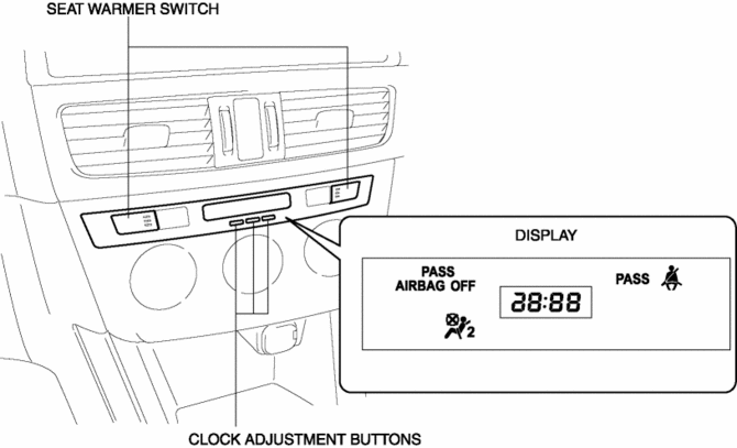
The clock displays the current time, the passenger and rear seat belt status, the passenger air bag deactivation (PAD) switch status, and the seat warmer operation status to notify the user.
Function
-
Stores the time set by the user and displays the current time.
Seat belt warning light function
-
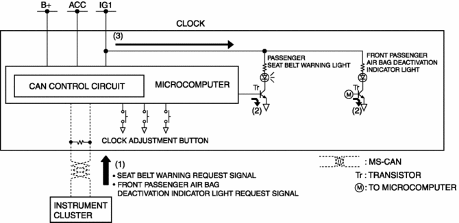
When the clock receives a seat belt warning light request signal sent via CAN transmission from the instrument cluster, it illuminates the seat belt warning light.
Front passenger air bag deactivation indicator light function
-
When the clock receives a front passenger air bag deactivation indicator light request signal sent via a CAN signal from the instrument cluster, it illuminates the front passenger air bag deactivation indicator light.
Construction
-
Consists of the display which displays the current time and indicator/warning lights, the clock adjustment button, and the seat warmer switch (with seat warmer).
-
Assembled to the climate control unit.
Operation
-
The clock displays the current time when the ignition is switched to ACC or ON (engine off or on).
Warning/indicator light operation
-
The clock receives (1) a seat belt warning request signal and front passenger air bag deactivation indicator light request signal from the instrument cluster.
-
The clock microcomputer turns the transistor on (2) based on each signal.
-
When the transistor turns on, a ground circuit with each warning/indicator light is established, and the warning/indicator light illuminates (3).
Seat warmer switch
-
For details on the seat warmer switch operation, refer to SEAT WARMER SYSTEM.
Fail-safe
-
Function not equipped.
 Active Command Modes Inspection [Instrument Cluster]
1. Connect the M-MDS to the DLC-2.
2. After the vehicle is identified, select the following items from the initialization
screen of the M-MDS.
a. Select “DataLogger”.
b. Select “Modulesâ ...
 Clock Input/Output Check Mode
Activation procedure
Inspection
NOTE:
The clock input/output check mode is displayed in the following order and
returning to the previous screen is impossible.
If you want to ...
Other materials:
Accelerator Pedal Removal/Installation
1. Disconnect the negative battery cable..
2. Remove in the order indicated in the table.
1
APP sensor connector
2
Accelerator pedal
3. Install in the reverse order of removal. ...
Front Fender Junction Installation [Panel Replacement]
Symbol Mark
Installation Procedure
1. When installing new parts, measure and adjust the body as necessary to conform
with standard dimensions.
2. Drill holes for the plug welding before installing the new parts.
3. After temporarily installing new parts, make sure the related parts fit p ...
Power Window System Preliminary Inspection [Power Window System]
Manual Open/Close Function Inspection
STEP
INSPECTION
ACTION
1
Switch the ignition ON (engine off or on).
Operate the power window using the manual open/close function on
the power window main swit ...
