Mazda CX-5 Service & Repair Manual: Center Pillar Installation [Panel Replacement]
Symbol Mark

Installation Procedure
1. When installing new parts, measure and adjust the body as necessary to conform with standard dimensions.
2. Drill holes for the plug welding before installing the new parts.
3. After temporarily installing new parts, make sure the related parts fit properly.
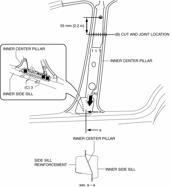
4. Insert the end of the inner center pillar locations indicated by (A) shown in the figure, between the inner side sill and side sill reinforcement.
5. Cut and join the area locations indicated by (B) shown in the figure.
6. Plug weld the 3 locations indicated by (C) shown in the figure.

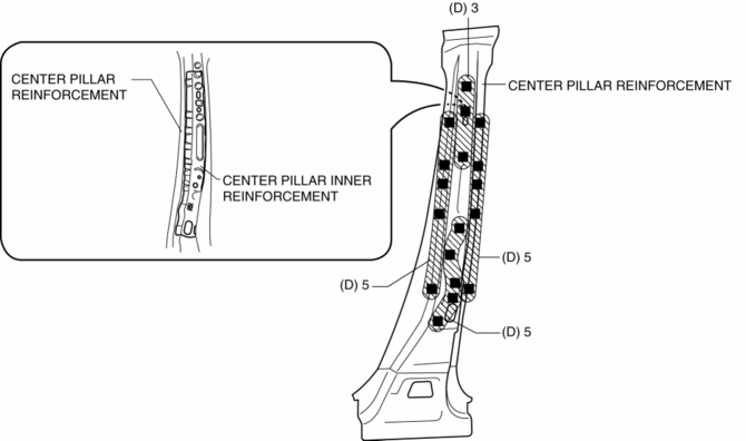
7. Plug weld the 18 locations indicated by (D) shown in the figure, then install the center pillar inner reinforcement to the center pillar reinforcement.

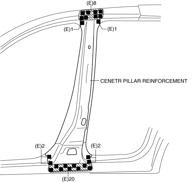
8. Plug weld the 34 locations indicated by (E) shown in the figure, then install the center pillar reinforcement.

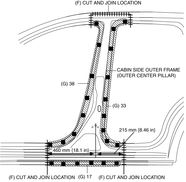
9. Cut and join the area locations indicated by (F) shown in the figure.
10. Plug weld the 88 locations indicated by (G) shown in the figure, then install the cabin side outer frame (outer center pillar).

 Cabin Side Frame Straight Line Dimensions [Dimensions]
Point symbol
Designation
Hole diameter or bolt or nut size mm {in}
A
Front side frame outer datum hole
?12 { ...
 Center Pillar Removal [Panel Replacement]
Symbol Mark
Removal Procedure
CAUTION:
Remove the curtain air bag module to prevent damage before servicing.
Front-side
Rear-side
CAUTION:
Avoid cutting with a bl ...
Other materials:
Front Bumper Reinforcement Removal/Installation
1. Disconnect the negative battery cable..
2. Remove the following parts:
a. Seal board upper.
b. Front bumper.
c. Front combination light.
d. Set plate.
e. Energy-absorbing form.
f. Front under cover No.1.
g. Bumper stiffener lower.
3. Support the shroud panel using a jack.
CAUT ...
Fuel Filler Pipe Removal/Installation
WARNING:
Fuel is very flammable liquid. If fuel spills or leaks from the pressurized
fuel system, it will cause serious injury or death and facility breakage. Fuel
can also irritate skin and eyes. To prevent this, always complete the “Fuel
Line Safety Procedure”, while referring ...
Pressure Control Valve Inspection [Skyactiv G 2.0]
1. Remove the pressure control valve assembly..
CAUTION:
Do not apply a pressure 36 kPa {0.37 kgf/cm2, 5.2 psi} or more. Doing so
will damage the pressure control valve and evaporative hose.
2. Apply a pressure of 36 kPa {0.37 kgf/cm2, 5.2 psi} to port A.
3. Verify that ther ...
