Mazda CX-5 Service & Repair Manual: Blind Spot Monitoring (Bsm) Off Indicator Light
Purpose
-
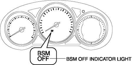
The BSM OFF indicator light informs the driver that the Blind Spot Monitoring (BSM) system is turned off or there is a malfunction in the system.
Function
-
The instrument cluster illuminates the BSM OFF indicator light based on the BSM system off signal sent via a CAN signal from the BSM control module (RH).
-
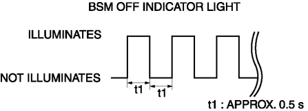
The instrument cluster flashes the BSM OFF indicator light based on the malfunction indication request signal sent via a CAN signal from the BSM control module (RH).
-
The flash pattern of the BSM OFF indicator light is as shown in the figure.

Construction
-
The BSM OFF indicator light are equipped in the instrument cluster.

Operation
-
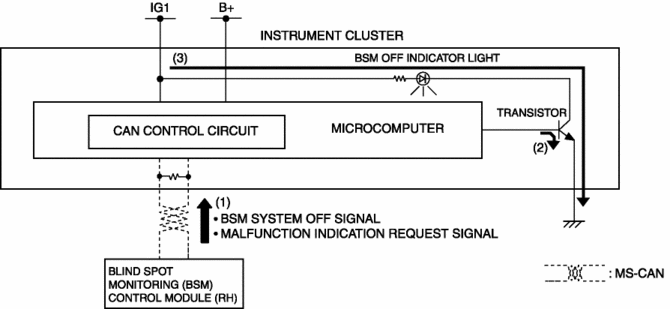
The instrument cluster receives (1) the BSM system off signal or malfunction indication request signal from the BSM control module (RH) via the CAN signal.
-
The instrument cluster turns the transistor on (2) intermittently for a malfunction indication request signal and continuously for a BSM system off signal.
-
When the transistor turns on intermittently, the BSM OFF indicator light flashes (3) and when it turns on continuously, the BSM OFF indicator light illuminates (3).

Fail-safe
-
Function not equipped.
 Blind Spot Monitoring (Bsm) Control Module Removal/Installation
1. Disconnect the negative battery cable..
2. Remove the rear combination light..
3. Remove the rear bumper..
4. Disconnect the connector.
5. Remove the nuts.
6. Remove the BSM control m ...
 Blind Spot Monitoring (Bsm) Off Switch
Purpose
The blind spot monitoring (BSM) system can be turned on or off optionally
by the driver.
Function
The switch operation signal is sent to the instrument cluster.
Co ...
Other materials:
Evaporator Temperature Sensor Inspection [Manual Air Conditioner]
NOTE:
Inspect the evaporator temperature sensor when it is installed to the A/C
unit.
1. Set the fan speed at MAX HI.
2. Set the temperature control at MAX COLD.
3. Set the RECIRCULATE mode.
4. Turn the A/C switch off.
5. Close all doors and windows.
6. Wait for 5 min.
7 ...
Outer Mirror Garnish Removal/Installation
1. Disconnect the negative battery cable..
2. Remove the outer mirror glass..
3. Insert a tape-wrapped flathead screwdriver into the upper outer mirror garnish
and remove tab A, B, C, D in the direction of arrow (1).
4. Insert a tape-wrapped flathead screwdriver into the upper outer mirr ...
Rear Washer Nozzle Removal/Installation
1. Disconnect the negative battery cable..
2. Remove the liftgate upper trim..
3. Remove the rear spoiler..
4. Disconnect the rear washer hose from the rear washer nozzle..
5. While pressing tabs of the rear washer nozzle in the direction of the arrows
(1) shown in the figure, pull the rea ...
