Mazda CX-5 Service & Repair Manual: Auto Light System
Outline
-
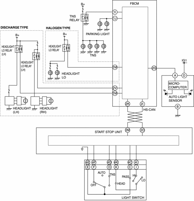
The auto light system automatically turns the TNS and headlights on/off according to the illumination level above and in front of the vehicle.
-
The auto light system is controlled by the front body control module (FBCM).
-
The front body control module (FBCM) performs auto light system fail-safe..
Structural View

System Wiring Diagram
Function
-
The auto light system receives a headlight illumination/off request signal from the auto light sensor and the front body control module (FBCM) turns the headlights on and off.
-
If the upward and forward illumination sensors detect the illumination level at which the headlights should be illuminated/turned off, the auto light sensor sends a headlight illumination/off request signal.
-
If the auto light sensor detects that the vehicle is being driven at night after sending the headlight illumination request signal, it switches to the night mode and changes the headlight off conditions so that the headlights do not turn off and on repeatedly due to temporary brightness from street lights or store lighting, making it difficult for the headlights to turn off.
Night mode
-
When the upward and forward illumination level sensors detect an illumination level of approx. 2,000 lux or less for approx. 10 min after sending the headlight illumination request signal, the auto light sensor determines that the vehicle is being driven at night and the auto light system is switched to the night mode.
-
The auto light sensor determines the headlight off condition based on the average illumination level for the previous 3 min detected by the upward and forward illumination level sensors while in the night mode.
-
If the average illumination level of the calculated past 3 min is approx. 4,000 lux or more, the auto light sensor cancels the night mode and sends a headlight off request signal.
-
When a headlight switch OFF signal is input while in the night mode, the auto light sensor cancels the night mode.
CAUTION:
-
If the vehicle is driven a long-distance in a tunnel, the traffic is congested inside a tunnel, or the environment (temperature, buildings, tree shadows) surrounding the vehicle is dark for approx. 10 min, even if the surroundings are bright during daytime, the conditions for driving at night will be met and the auto light sensor may switch to the night mode.
-
Because turning off of the headlights is determined by the average illumination level for the past 3 min when the mode is switched to the night mode during daytime while the surrounding area is bright, if the vehicle is driven in an environment (temperature, buildings, or tree shadows) surrounding the vehicle which is dark, the average illumination level may be insufficient and the condition for turning off the headlights may not be met, therefore the night mode may not cancel (headlights continue to illuminate).
-
Operation
-
The auto light system operates when the ignition is switched ON and the light switch is in the AUTO position.
Illumination operation
NOTE:
-
The following illumination level is for reference because it varies depending on the surrounding conditions (weather, reflection off buildings).
-
The illumination level sensitivity of the auto light sensor can be changed. The illumination level shown below is the “Medium” set value..
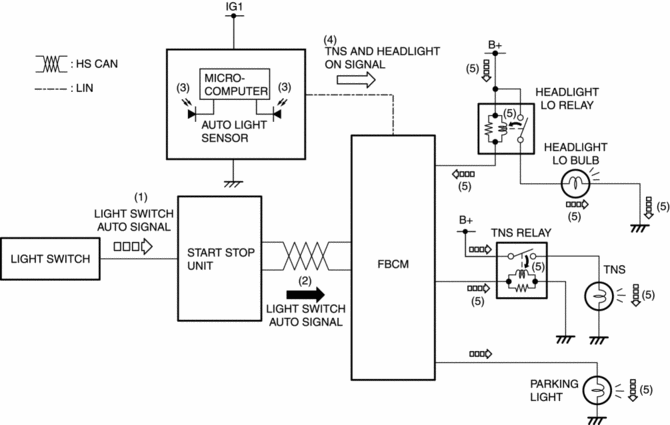
1. When the light switch is operated to the AUTO position with the ignition switched ON (engine off or on), a light switch AUTO signal is input to the start stop unit.
2. The start stop unit sends the light switch AUTO signal to the front body control module (FBCM) as a CAN signal.
3. The auto-light sensor detects the illumination level above and in front of the vehicle.
4. When the auto light sensor detects an illumination level of approx. 2,000 lux or less, it sends a TNS and headlight on signal to the front body control module (FBCM) as a LIN signal.
5. When the front body control module (FBCM) receives a headlight on signal, it turns the TNS relay and headlight LO relay on and illuminates the TNS, Parking light, and headlights.
Lights off operation
NOTE:
-
The following illumination level is for reference because it varies depending on the surrounding conditions (weather, reflection off buildings).
-
The illumination level sensitivity of the auto light sensor can be changed. The illumination level shown below is the “Medium” set value..
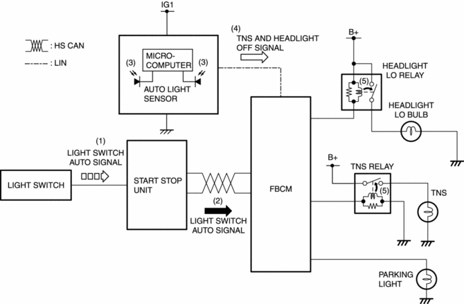
1. When the light switch is operated to the AUTO position with the ignition switched ON (engine off or on), a light switch AUTO signal is input to the start stop unit.
2. The start stop unit sends the light switch AUTO signal to the front body control module (FBCM) as a CAN signal.
3. The auto-light sensor detects the illumination level above and in front of the vehicle.
4. When the auto light sensor detects an illumination level of approx. 4,000 lux or more for 1.5—2.5 s, it sends a headlight off signal to the front body control module (FBCM) as a LIN signal.
5. When the front body control module (FBCM) receives a headlight off signal, it turns the TNS and headlight LO relay off and turns the TNS, Parking light, and headlights off.
 Auto Light Off System
Purpose
The auto light-Off system turns off the TNS or headlights automatically.
The front body control module (FBCM) performs auto light-Off system fail-safe..
Function
Th ...
 Cargo Compartment Light
Purpose
The cargo compartment light illuminates the cargo room interior when the
liftgate is opened.
Function
When the liftgate is opened, illuminates by the cargo room light sw ...
Other materials:
Bsm Indicator Light Flashes While Not Under Bsm Indicator Light Flashing Conditions
(No Combination Switch Operation (Turn Signal Switch)) [Blind Spot Monitoring (Bsm)]
Description
BSM indicator light flashes while not under BSM indicator light-flashing
conditions (no combination switch operation (turn signal switch)
The BSM indicator light flashes despite not satisfying the BSM indicator
light flashing ...
Shroud Upper Reinforcement Removal [Panel Replacement]
Symbol Mark
Removal Procedure
1. Drill the 4 locations shown in the figure.
NOTE:
When drilling the 4 locations shown in the figure, do not drill a hole all
the way through or there could be a problem when installing the new part.
2. Remove the shroud upper reinforcement ...
Water Pump Removal/Installation
WARNING:
Never remove the cooling system cap or loosen the radiator drain plug while
the engine is running, or when the engine and radiator are hot. Scalding engine
coolant and steam may shoot out and cause serious injury. It may also damage
the engine and cooling system.
Tu ...
