Mazda CX-5 Service & Repair Manual: Antenna Feeder No.2 Inspection
1. Disconnect the negative battery cable..
2. Remove the following parts:
a. A-pillar trim (RH).
b. Trunk board.
c. Trunk end trim (RH).
d. Rear scuff plate (RH).
e. Trunk side trim (RH).
3. Disconnect antenna feeder No.1.
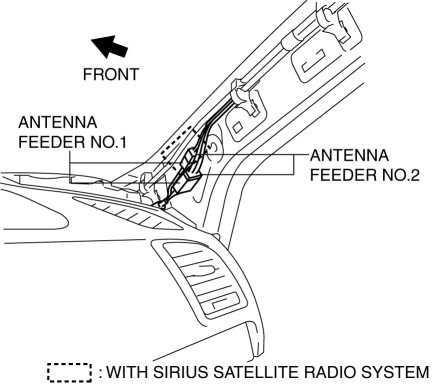
4. Disconnect antenna feeder No.3.
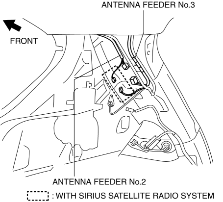
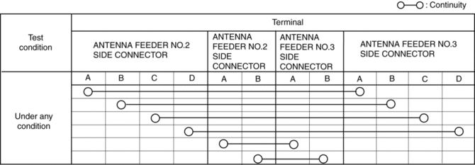
5. Verify that the continuity between antenna feeder No.2 terminals is as indicated in the table.
-
If not as indicated in the table, replace antenna feeder No.2.
 Antenna Feeder No.1 Removal/Installation
With audio system
1. Disconnect the negative battery cable..
2. Remove the following parts:
a. Side speaker grille (RH).
b. Tweeter (RH).
c. A-pillar trim.
d. Passenger-side front scuff pla ...
 Antenna Feeder No.2 Removal/Installation
Removal
1. Disconnect the negative battery cable..
2. Remove the following parts:
a. Sunroof seaming welt (with sunroof system).
b. A-pillar trim.
c. Front map light.
d. Sunvisor.
e. Fron ...
Other materials:
Traction Control System (TCS)
The Traction Control System (TCS) enhances traction and safety by controlling
engine torque and braking.
When the TCS detects driving wheel slippage, it lowers engine torque and operates
the brakes to prevent loss of traction.
This means that on a slick surface, the engine adjusts automaticall ...
Airflow Mode Control [Full Auto Air Conditioner]
Purpose
The airflow mode control changes the airflow mode according to the vehicle
environment.
Function
The airflow mode control drives the airflow mode actuator according to the
mode switch, defroster switch, and the vehicle environment and switches the
position of the ...
Caliper (Front) Disassembly/Assembly
1. Disassemble in the order indicated in the table.
1
Bleeder cap
2
Bleeder screw
3
Piston
(See Piston Disassembly Note.)
4
Dust seal
5
Piston seal
...
