Mazda CX-5 Service & Repair Manual: Air Fuel Ratio (A/F) Sensor Inspection
A/F Sensor Inspection
1. Connect the M-MDS to the DLC?2.
2. Switch the ignition ON (engine on).
3. Warm up the engine to normal operating temperature.
4. Access the following PIDs using the M-MDS..
-
VSS (Vehicle speed)
-
RPM (Engine speed)
-
O2S11 (A/F sensor output current)
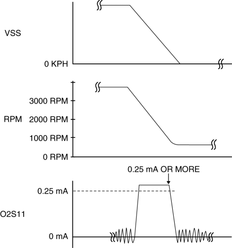
5. Drive the vehicle and decelerate the engine speed by releasing the accelerator pedal fully when the engine speed is 3,000 rpm or more
.
6. Verify that the A/F sensor output current (PID: O2S11) is 0.25 mA or more
while decelerating as shown in the figure.

-
If not as specified, replace the A/F sensor..
A/F Sensor Heater Inspection
WARNING:
-
A hot engine and exhaust system can cause severe burns. Turn off the engine and wait until they are cool before removing the exhaust system.
1. Disconnect the negative battery cable..
2. Disconnect the A/F sensor connector.
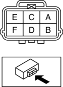
3. Measure the resistance between A/F sensor terminals A and E.

-
If not as specified, replace the A/F sensor..
-
A/F sensor heater resistance
-
1—10 ohms [normal temperature]
 Air Fuel Ratio (A/F) Sensor Heater Control
Outline
Based on the control of the A/F sensor heater, a stabilized oxygen concentration
is detected even at low exhaust temperatures, and feedback control of fuel injection
even at cold ...
 Air Fuel Ratio (A/F) Sensor Removal/Installation
WARNING:
A hot engine and exhaust system can cause severe burns. Turn off the engine
and wait until they are cool before removing the exhaust system.
CAUTION:
Do not allow fla ...
Other materials:
Front Door Key Cylinder Removal/Installation
1. Disconnect the negative battery cable..
2. Remove the service hole cover.
3. Detach the screw from the front door key cylinder.
NOTE:
The screw cannot be removed because the front outer handle bracket has a
stopper which prevents the screw from falling.
4. While pre ...
Engine Front Cover
Purpose, Function
The engine front cover covers the front of the engine to prevent engine oil
spillage, noise leakage, and foreign material penetration.
Construction
The engine front cover is installed to the front of the engine.
The lightweight engine front ...
Barometric Pressure (Baro) Sensor Inspection
Voltage Inspection
NOTE:
Because the BARO sensor is integrated in the PCM, replacing the BARO sensor
includes replacement of the PCM.
1. Connect the M-MDS to the DLC?2.
2. Switch the ignition ON (engine off or on).
3. Verify that the BARO sensor output voltage (PID: BARO) is wi ...
