Mazda CX-5 Service & Repair Manual: Adaptive Front Lighting System (Afs) Off Switch Inspection
1. Disconnect the negative battery cable..
2. Remove the switch panel..
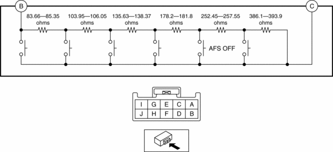
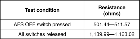
3. Verify that the resistance between AFS OFF switches B and C is as indicated in the table.
-
If the resistance can be verified as indicated in the table, go to the next step.
-
If not as indicated in the table, replace the cluster switch.
4. Apply battery positive voltage to AFS OFF switch terminal J, and connect terminal I to ground.
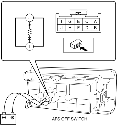
5. Verify that the LED illuminates.
-
If the LED does not illuminate, replace the cluster switch.

 Auto Light Sensor
Purpose
The auto light sensor detects the illumination level above and in front of
the vehicle and outputs it to the front body control module (FBCM).
Function
The auto-light se ...
Other materials:
Shroud Side Member Installation [Panel Replacement]
Symbol Mark
Installation Procedure
1. When installing new parts, measure and adjust the body as necessary to conform
with standard dimensions.
2. Drill holes for the plug welding before installing the new parts.
3. After temporarily installing new parts, make sure the related parts fit p ...
HomeLink Wireless Control System
NOTE
HomeLink and HomeLink house are registered trademarks of Johnson Controls.
The HomeLink system replaces up to 3 hand-held transmitters with a single builtin
component in the auto-dimming mirror.
Pressing the HomeLink button on the auto-dimming mirror activates garage doors,
gates and oth ...
Front Shock Absorber And Coil Spring Disassembly/Assembly
WARNING:
Removing/installing the front shock absorber and coil spring is dangerous.
The front shock absorber and coil spring could fly off and cause serious injury
or death, and damage the vehicle.
1. Remove the front shock absorber and coil spring..
2. Remove in the order ...
